And now for something completely different

Talk about musical instrument construction, setup and repair.

Moderators: kiwigeo, Jeremy D

User avatar
Nick
Blackwood
Posts: 3642
Joined: Thu Feb 26, 2009 11:20 am
Location: Christchurch, New Zealand
Contact:

Re: And now for something completely different

Post by Nick » Wed Oct 12, 2011 5:55 am

charangohabsburg wrote:Yeah. Of course a sturdy high tech wire, maybe of titanium, one of those they use in NZ for monstersheep fences ;). Or also a welded solid machined rigid hook if you like this more. But at the moment I don't grab it why it must be 90°-turnable and removable.
These things stick 20mm up in the air Markus & are only 3mm x 6mm wide at their base so I'm guessing (or covering the possibility) that they could get knocked or damaged so I wanted to 'build in' some replace-ability to cover future eventualities. The fact that they turn through 90 degrees is my way of being able to change & lock them in place easily without making the design too complex. Any permanent fitting would require major work to replace at a later date, this way the owner can change their own in a few seconds.
J F Custom wrote:Oh, and my wife wants one... "Pretty please" she said. :roll:

I've told her I think it may be worth a few ukes to trade... :lol:
:lol: :lol: Just a few Ukes but I'm willing to negotiate......she did say pretty please! :wink:
"Jesus Loves You."
Nice to hear in church but not in a Mexican prison.

User avatar
charangohabsburg
Blackwood
Posts: 1818
Joined: Sat Oct 16, 2010 1:25 am
Location: Switzerland

Re: And now for something completely different

Post by charangohabsburg » Wed Oct 12, 2011 10:41 am

Thanks for the explanation Nick. Those things look so sturdy to me that I did not think even a second of the possibility that they could get damaged!
Markus

To be stupid is like to be dead. Oneself will not be aware of it.
It's only the others who suffer.

User avatar
kiwigeo
Admin
Posts: 10596
Joined: Sat Sep 29, 2007 5:57 pm
Location: Adelaide, Sth Australia

Re: And now for something completely different

Post by kiwigeo » Wed Oct 12, 2011 11:37 am

charangohabsburg wrote:Thanks for the explanation Nick. Those things look so sturdy to me that I did not think even a second of the possibility that they could get damaged!
like everything else in Christchurch this baby has to be engineered to withstand a magnitude 7 earthquake.....
Martin

User avatar
Nick
Blackwood
Posts: 3642
Joined: Thu Feb 26, 2009 11:20 am
Location: Christchurch, New Zealand
Contact:

Re: And now for something completely different

Post by Nick » Fri Oct 21, 2011 2:16 pm

And so the story continues................All the sockets are welded in & I made some Stainless steel cam pins (a small area has been turned down "off centre") which are located at each end of the line of hooks so that the cord has a smooth transition around the 'corner'.
IMG_2062.JPG
IMG_2062.JPG (49.11 KiB) Viewed 15974 times
IMG_2063.JPG
IMG_2063.JPG (42.84 KiB) Viewed 15974 times
This pretty much completed the frame rails so I've now moved onto making the resonator assemblies, once again the two sides (natural notes & sharps) are pretty much identical so I'll only show the one assembly being made. The only variation from the path I've made from Jim McCarthy's set is that on the sharps side he (and several other makers I've noted) only have resonator tubes below the bars that are there (Think of the black notes on a piano) so there are gaps. Just to keep the continuity going, mainly for my own anal aesthetics :roll: , I've cut tubes to go into the empty spaces, these won't have 'fans' or end plugs in them, they will just be there for looks and continuity as this will be the 'front' of the vibes that the audience see.
The resonator tubes have to be the same internal diameter as their respective bar's widths above them and seeing as these are 3 different widths, so too are the tubes below them. So I've made up some rails that the tubes will be fixed to & put bends in them so that they step down for the different diameter tubes. The blocks at each end have locating pins sticking out of the underside, these pins in turn locate in holes drilled into the cross rails. To keep any extrenuous vibrations out I've used the little rubber 'top hats' again that I used for the underside of the frame rails (seen as the little black things in the picture).
Here's a picture with one of the resonator tubes just sitting in there for effect :wink:
IMG_2057.JPG
IMG_2057.JPG (76.94 KiB) Viewed 15974 times
IMG_2058.JPG
IMG_2058.JPG (64.24 KiB) Viewed 15974 times
And an end on shot giving a better idea of what I was trying to explain about the stepdowns (a picture is definitely worth a thousand of my words!)
IMG_2059.JPG
IMG_2059.JPG (71.21 KiB) Viewed 15974 times
I've cut all the resonator tubes to their respective lengths, I've made mine longer than Jim McCarthy specifies in his excellent 'homebuilt' instructions. In his build he uses PVC downpipes for the resonators & just glues PVC caps on the ends then adjusts the total length (by cutting material from the open end) to get the tuning right. I've decided that I'll make some adjustable 'plugs' that will rely on sandwhiching an 'O' ring between two discs to effect a tight fit. Tuning can be effected by finding the right spot for the plug to be then tightening it up which will lock it in place. Any seasonal effects (temperature swings) on the tuning (as the aluminium expands or contracts) of the resonators can be 'corrected' by altering the plug positions, unfortunately there's not a lot of compensation that be built into the bars so these may still go out a fraction (standard for these instruments if they see temperature extremes apparently) :(
Resonators cut & roughly cleaned up, these will eventually be powder coated.
IMG_2061.JPG
IMG_2061.JPG (70.97 KiB) Viewed 15974 times
Next step will be to cut slots in the top end of these to allow for the shaft that drives the fans to pass through. Hopefully the next lot of pics I post up will show this and the tubes all in place.
"Jesus Loves You."
Nice to hear in church but not in a Mexican prison.

User avatar
kiwigeo
Admin
Posts: 10596
Joined: Sat Sep 29, 2007 5:57 pm
Location: Adelaide, Sth Australia

Re: And now for something completely different

Post by kiwigeo » Fri Oct 28, 2011 1:01 pm

Yesterday I popped into Nick's workshop hoping to catch him. Unfortunately he was out "shopping" but one of the other workshop boys showed me the vibe. The photos of this instrument look impressive but when you see it in real life it looks even better...and you start to appreciate the work that has gone into it.
Martin

User avatar
Nick
Blackwood
Posts: 3642
Joined: Thu Feb 26, 2009 11:20 am
Location: Christchurch, New Zealand
Contact:

Re: And now for something completely different

Post by Nick » Fri Nov 04, 2011 2:44 pm

Ok, this latest installment has a fair bit of progression on it, all to do with the resonators. The resonators have the rotating shaft that the fans mount to running through the tops of them so I had to cut a clearance slot in them. I've managed to incorporate some aspect of my guitar building side into this! I've salvaged an offcut of some laminated MDF I had when I made up my body molds & turned it down into plugs of various diameters to sit inside the tube while I clamped it in the vice to machine it. These tubes are only 1.2mm wall thickness & unless I had something in there filling the hole it would have crushed the tube, it was then just a simple matter of running a cutter in to the required depth.
IMG_2064.JPG
IMG_2064.JPG (62.25 KiB) Viewed 15886 times
Once all the tubes had been slotted I made a dummy rod the same size as my slots so that I could sit this inbetween the two side rails of the resonator rack so that my slots would line up along the correct axis
IMG_2066.JPG
IMG_2066.JPG (59.3 KiB) Viewed 15886 times
With the 'dummy' in place I marked on the resonator rails where each bar sat above them, as the resonators have to be directly under their respective bar. Once I had all the positions marked it was just a matter of Tig welding the tubes in place.
A bit of George Zamfir anybody? :lol:
IMG_2073.JPG
IMG_2073.JPG (76.09 KiB) Viewed 15886 times
For the fan shaft I used some 6mm round Stainless. I had plenty of the 6mm bearings I've used throughout, so have kept as much 'standardised' as I can. I made up some little carrier brackets that sit between the resonator rails & hold the bearings
IMG_2071.JPG
IMG_2071.JPG (46.38 KiB) Viewed 15886 times
Next came making the pulleys to drive the shaft! I made these with a groove that was 30mm at it's base which gives me a 3:1 reduction ratio, I can make smaller pulleys if this doesn't give the customer a satisfactory speed range.
IMG_2077.JPG
IMG_2077.JPG (50.24 KiB) Viewed 15886 times
I've used ordinary O rings as the drive as the resonators sit between the side rails at an angle so O rings are best equiped to handle this 'misalignment'
After I had this in place I had to make the fans (or butterflys as some call them) that mount to this shaft. It is these that open & shut the resonator tubes giving the instrument it's name as it causes a vibrato effect. I was originally going to machine flats on the 6mm rod & mount the discs onto the flat but decided against it as I felt it could compromise the bar's strength & reduce it's resistance to getting bent :shock:. I utilised Jim Mc Carthy's of 'bending' Ally discs over the bar but refined his technique a tad (Jim hammers thin ally sheet over his shafting) :oops: .Being a tool & diemaker by trade I decided to make a tool that did that for me :wink: I made a form that mounted into our fly press with the 'female' part of the disc machined into it & sunk a bit of the shafting into a scrap bit of the 12mm plate to the right depth so that when the disc was formed over it, the centreline of the material's thickness was on the same centreline as the shaft. The fan blanks I punched out on a commercial hole punch (the blanks start out oversize as the punches aren't spot on for the sizes I want but they get machined to size later anyway) I fortunately have access to then drilled a hole in the centre, this not only will provide a mounting point later but acts as an 'index' for allignment during the forming process.
My 'setup' for the fans
IMG_2082.JPG
IMG_2082.JPG (79.79 KiB) Viewed 15886 times
The blanks are placed over the locating pin of the bottom half
IMG_2087.JPG
IMG_2087.JPG (52.53 KiB) Viewed 15886 times
The top is brought down
IMG_2088.JPG
IMG_2088.JPG (43.89 KiB) Viewed 15886 times
Et Viola, one oversized fan
IMG_2090.JPG
IMG_2090.JPG (41.01 KiB) Viewed 15886 times
Not only did I start with too big a blank because of the punch sizes I was limited to, but it also helped because as you can imagine, the what was once round blank, has now been shortened across one of it's axis. So allowing a bit extra, I was able to machine down to size & turn an oval blank back into a round fan. I again utilised my MDF plugs for this operation by maching a 'half round' into one end & putting a locating pin in at the centre (aligning the blank centrally)
IMG_2094.JPG
IMG_2094.JPG (45.96 KiB) Viewed 15886 times
I then just cut out a blank piece of MDF & drove the tailstock centre into it, this then allows me to 'sandwhich' the blank & turn it down to size.
IMG_2095.JPG
IMG_2095.JPG (48.11 KiB) Viewed 15886 times
And here we have some of the finished fans
IMG_2096.JPG
IMG_2096.JPG (69.51 KiB) Viewed 15886 times
I then placed them onto the shaft & centrally within their respective resonators to mark the central hole position. Once I had the positions I drilled and tapped 3mm holes (these had to be in the same plane so that all the fans were aligned) in all the positions & screwed the fans to the shaft. The fans alternate, one is screwed from one side of the shaft & the neighbouring one is screwed from the other side, this is meant to sort out any imbalance issues.
IMG_2100.JPG
IMG_2100.JPG (56.71 KiB) Viewed 15886 times
I'm currently sorting out some timing issues I've found I have with these(one bank of fans gets out of sync with the other :oops: ), not sure if the commercial ones do sync together or not but I cant imagine it would sound particularly nice if you had two different vibrato timings going on as you play :shock: My solution is to use a small timing belt (toothed belt) & pulleys on the input side of things. This will require some replacement of some of my designed parts with the appropriate parts but not a major problem, I'll post some pics of this as I go. Another part that is now completed is the isolator/insulator that goes over the hooks, I managed to get hold of some rubber tubing & cut it up into much smaller lengths, this is isolates the bars from the possiblity of touching the metal hooks & also holds each bar centralised in it's place.
IMG_2079.JPG
IMG_2079.JPG (50.4 KiB) Viewed 15886 times
Anyway, that's where I'm at so far but it's definitely getting closer to completion, once I'm happy with the fan/vibrato timing it's just a matter of tuning the bars and making up some adjustable plugs for the resonators. Then it's off to the powder coaters & Anodisers respectively. Hope you guys are still finding some interest in this thread! :D
"Jesus Loves You."
Nice to hear in church but not in a Mexican prison.

User avatar
Clancy
Blackwood
Posts: 620
Joined: Wed Dec 17, 2008 10:26 am
Location: Canberra

Re: And now for something completely different

Post by Clancy » Fri Nov 04, 2011 3:00 pm

Hope you guys are still finding some interest in this thread!
Are you kidding!! Bring it on!!!
Craig
I'm not the sharpest tool in my shed

User avatar
matthew
Blackwood
Posts: 1192
Joined: Mon Oct 08, 2007 1:16 pm
Location: Sydney, Inner West
Contact:

Re: And now for something completely different

Post by matthew » Fri Nov 04, 2011 10:17 pm

watching with awe and smacking gob at same time.

User avatar
Kim
Admin
Posts: 4376
Joined: Wed Sep 26, 2007 8:32 pm
Location: South of Perth WA

Re: And now for something completely different

Post by Kim » Fri Nov 04, 2011 11:25 pm

Interesting??? Try fascinating..... better yet...Inspiring!!

I am certain that we have many quieter members and lurkers alike who would agree with me that this is one of the most entertaining thread of all at the ANZLF and we all appreciate your time and effort to share.

Cheers 8)

Kim

User avatar
charangohabsburg
Blackwood
Posts: 1818
Joined: Sat Oct 16, 2010 1:25 am
Location: Switzerland

Re: And now for something completely different

Post by charangohabsburg » Sat Nov 05, 2011 12:52 am

Nick wrote:Hope you guys are still finding some interest in this thread! :D
:roll:

I hope you will not stop when I tell you that I don't have "some" interest in this thread - I have much interest in it!

Thanks a lot for taking your time to explain the whole process. Image Image Image Image Image Image Image Image
Markus

To be stupid is like to be dead. Oneself will not be aware of it.
It's only the others who suffer.

User avatar
Nick
Blackwood
Posts: 3642
Joined: Thu Feb 26, 2009 11:20 am
Location: Christchurch, New Zealand
Contact:

Re: And now for something completely different

Post by Nick » Mon Nov 07, 2011 5:58 pm

I'm glad people are still enjoying this build, never too sure if it's got too much info or pics (which can be boring) or never enough :shock: But it looks like I seem to be hitting the right balance!
Ok spent Saturday 'correcting' the input drive system to a timed belt drive. The only toothed belt I could get locally somewhere close to where I wanted it was still too wide (I wanted approx 6mm wide & the supplier only had 3/8") so with scalpel in hand I carefully cut it down in width, it's not perfect (width varies as I cut only by hand) but the belts are fairly cheap so I'll make a proper cutting jig & cut another more accurately later.For the time being my 'wobbly one side' belt will do to get things running & the design fine tuned. The dinky pulley was slightly smaller in diameter than my own grooved pulley but this doesn't affect the final fan speed as long as both pulleys are the same. So I had 4 pulleys (two originals & two toothed new ones), how to 'connect' them ?
IMG_2103.JPG
IMG_2103.JPG (46.08 KiB) Viewed 15807 times
I decided to machine the original outside 'driving' groove off my larger pulley & machine a recess in the face of it. I would then machine the commercial toothed pulley down in width & at the same time machine a spigot on it that was a nice press fit into the recess of the larger pulley. Just to make sure nothing moved or rotated I utilised the original grub screw hole & made sure my recess went into this area so that when the grub screw was in & doing it's job of locking onto the driveshaft, it went through both pulleys.
Pulleys machined & ready to be pressed together
IMG_2104.JPG
IMG_2104.JPG (40.56 KiB) Viewed 15807 times
And the the deed was done! No going back from here unless I completely machined the new pulley off :?
IMG_2105.JPG
IMG_2105.JPG (36.84 KiB) Viewed 15807 times
The first pulley in place, this also takes the drive from the motor
IMG_2107.JPG
IMG_2107.JPG (45.03 KiB) Viewed 15807 times
Fortunately the belt was pretty damn close in diameter to the correct size I needed (my pulleys are at fixed centres), it just meant I had a small amount of slack to adjust out so I used one of the blank area's of the box section to mount an adjuster which was basically yet another of my spare 6mm bearings, I made a small pin to go through it & tapped a hole up its centre, this allows it to be slid up or down then just tighten screw when things are right.
IMG_2110.JPG
IMG_2110.JPG (50.02 KiB) Viewed 15807 times
Things get a little tight as far as the belt goes for my liking so I've ordered some bearings with a smaller OD so that I have a little more adjustment in the downwards direction. It all seems to work nicely so that was time not wasted :oops:

Next step is to machine up the adjustable plugs, these are all identical except for their diameters (3 different resonator diameters don't forget!) so I'll only show one of them to give you the idea. I've machined some Ally 'flanges' with a taper on the inside face, an 'O' ring gets sandwhiched between these tapered faces. When a cap screw gets tightened it pulls the two flanges together expanding the 'O' ring out so that it grips the tube. Adjusting or shifting the plug will just be a matter of loosening the screw quarter of a turn or so & sliding either further up or down the tube until the correct relationship with the tuned bar above is reached.
The 'items' that make up one plug.
IMG_2111.JPG
IMG_2111.JPG (49 KiB) Viewed 15807 times
And with the screw in & tightened.
IMG_2113.JPG
IMG_2113.JPG (34.2 KiB) Viewed 15807 times
Well that's where I'm at so far & I've got more of the smaller plugs to machine but once that's done it's onto tuning up the bars, the part that will make or break the whole instrument! Forunately I have spare plate so if anything does go wrong I've got spare material! :gui
"Jesus Loves You."
Nice to hear in church but not in a Mexican prison.

Kamusur
Blackwood
Posts: 754
Joined: Thu Dec 30, 2010 10:08 pm

Re: And now for something completely different

Post by Kamusur » Tue Nov 08, 2011 10:01 am

Absolutely staggering, what a piece of workmanship!

Steve

User avatar
DarwinStrings
Blackwood
Posts: 1877
Joined: Thu Nov 13, 2008 10:27 pm
Location: Darwin

Re: And now for something completely different

Post by DarwinStrings » Wed Nov 09, 2011 10:39 am

Interlude


youtu.be/

Jim
Life is good when you are amongst the wood.
Jim Schofield

User avatar
charangohabsburg
Blackwood
Posts: 1818
Joined: Sat Oct 16, 2010 1:25 am
Location: Switzerland

Re: And now for something completely different

Post by charangohabsburg » Wed Nov 09, 2011 11:06 am

DarwinStrings wrote:Interlude
Yeah, great! :D

And if Chick Corea is lucky, one day he'll play Nick's vibraphone! ;)


youtu.be/
Markus

To be stupid is like to be dead. Oneself will not be aware of it.
It's only the others who suffer.

User avatar
christian
Blackwood
Posts: 338
Joined: Wed Oct 20, 2010 10:31 am
Location: Bay of Islands NZ
Contact:

Re: And now for something completely different

Post by christian » Wed Nov 09, 2011 12:24 pm

Nick although I know nothing about metal, your incredible engineering prowess and creative talent is clearly on show here.
amazing work mate !!!!

Christian.
Why does the eye see a thing more clearly in dreams than the imagination when awake?
Leonardo da Vinci

www.christiandruery.com

ckngumbo
Blackwood
Posts: 102
Joined: Mon Oct 26, 2009 11:41 am
Location: Florida US

Re: And now for something completely different

Post by ckngumbo » Thu Nov 10, 2011 12:59 pm

If I could come up with a something that hasn't been said I'd offer it up. All I can say is WOW!
Rob

User avatar
Nick
Blackwood
Posts: 3642
Joined: Thu Feb 26, 2009 11:20 am
Location: Christchurch, New Zealand
Contact:

Re: And now for something completely different

Post by Nick » Fri Nov 25, 2011 6:26 pm

Onto tuning of the bars! I won't go into the finer points of tuning the bars because A: I'm still only just coming to grips with the process myself so it would be wrong of me to say "do this & you must do that" & B: There's far more 'onto it' people than I that have researched this area and have published in various forms, one is James L Moore's Thesis paper entitled "Acoustics of bar percussion instruments" his thesis is available (& of which I bought a copy (yes US$ are exchanged!) & I got it to work in conjunction with Jim McCarthy's package). But for those of you that would like to know/read about the technicalities of shaping bars & where to remove material e.t.c. There's a really good paper written on the subject by a guy called Jeff La Favre here. It's about tuning Rosewood Marimba bars (he makes Marimbas for a living) but the theory is virtually identical, material is removed from certain area's of the underside of the bar to tune the various notes.
For those that don't want to dive into a 20+ page article :roll: , the basics are (from what I've read, remember, like I say I'm far from an expert! :wink: ): The lower Vibe bars up to C4 are tuned to a fundamental & the first harmonic (2 octaves above the fundamental) & a 3rd harmonic (2 octaves and a major third above the fundamental), middle bars are tuned to the fundamental & the first harmonic, my middle is in the D4-F5 range, I found that once I got to G5 it really starts getting harder to hear the harmonic. The upper range (G5-F6) are tuned to the fundamental only, any first harmonic would be so weak that you wouldn't hear it anyway! The arch is formed and by removing material from specific area's of the arch, I can tune the various modes. The fundamental is lowered by removing material from the central area of the bar, the first harmonic is lowered by removing material from the end radius's of the arch & the second harmonic is lowered by removing material from the side of the same radius.
I was chatting to Jim McCarthy (via email) who was wondering why, when I have access to all this equipment, I was going to do the arch's essentially by hand (Drill press & belt sander). I wanted to do this first set by hand, not only to get a feel for the process but also as this was the first time ever I've done a set of bars I have no baseline figures for the various sizes/dimensions but as I'm doing each of these bars I am taking various measurements so that if I have to ever do another set of bars or even another complete set of vibes I'll have all the numbers that I can 'rough out' the bars on a mill & just fine tune the last little bits by hand. I've left each bar a few cents sharp too as I'm not sure what effect anodizing will have on the tuning of the bars so at least I'll have a little elbow room to bring them down should the anodizing not alter anything. I noticed even Musser's have little 'patches' sanded on the arch to get everything smack on.
So enough drivel! :roll: lets throw a few pictures in :)
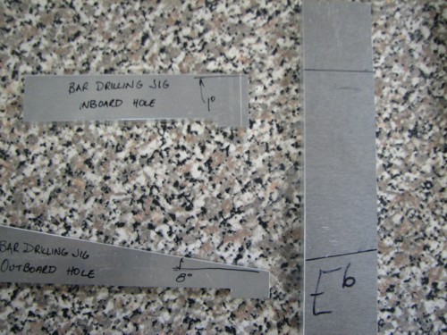
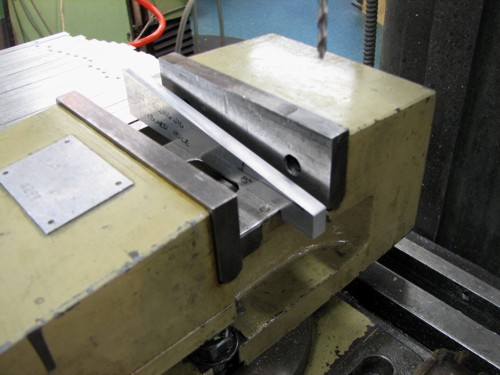
First I drilled the cross holes for the Nylon support line to pass through, each hole has to be drilled on an angle as the bar frames taper.
IMG_2114.JPG
IMG_2114.JPG (79.25 KiB) Viewed 15660 times
The little 'wedge' shaped bits of plate on the left are my drilling jigs/guides, these sit in my mill vice & the bar is placed onto them holding the bar on the right angle for drilling. The 'inboard' hole (nearest the centreline of the vibes) is drilled at a much lesser angle than the outboard hole so each bar required two jigs. I set one jig/guide up and drilled all of those holes then put the second one in & drilled the remaining holes.
IMG_2124.JPG
IMG_2124.JPG (54.6 KiB) Viewed 15660 times
And drilling the much steeper 'outboard' hole.
IMG_2126.JPG
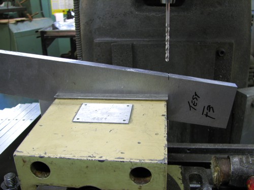
IMG_2126.JPG (51.55 KiB) Viewed 15660 times
Once all my cross holes were done I removed excess material from the centre of each bar by drilling holes similar to drilling the interior of an Archtop plate! I wasn't sure how far the drill out from the centreline so this was very much a drill abit, sand to remove the drill marks, check the tuning & drill a little more as needed sort of an operation. I over cooked a couple of the longer bars and had to remake them :oops: :oops: but that's what trial and error is all about I guess :lol:
Here are a few of the higher register bars either ready for drilling or semi-smoothed and ready for checking it's first tuning
IMG_2133.JPG
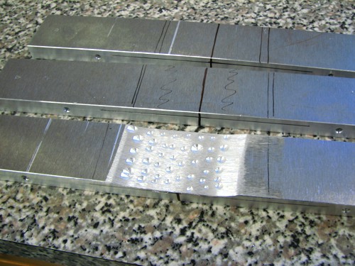
IMG_2133.JPG (72.24 KiB) Viewed 15660 times
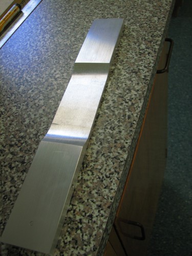
A selection of the lower register bars, I've sanded the arch to a semitone higher than the finished tone. After getting them to this stage I sanded the whole bar to 120 grit smoothness. Checked the tuning (I forgot to mention I use Peterson's excellent "StroboSoft" software to get my readings but this can be done with any standard chromatic guitar tuner) & noted on the bar the pitch ready for final sanding the arch.
IMG_2127.JPG
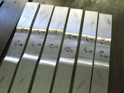
IMG_2127.JPG (59.19 KiB) Viewed 15660 times
The notation I wrote on each bar is pretty simple (has to be for me to understand it! :lol: )
IMG_2129.JPG
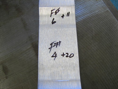
IMG_2129.JPG (51.38 KiB) Viewed 15660 times
I noted the pitch in the bar's first two positions, on this bar (F4) the fundamental is sitting in the F# range in the fourth octave and is 20 cents above the F#. The first harmonic is F# in the 6th octave & 11 cents high. I didn't worry about notating the second harmonic as this was pretty close to the first already & only needed a little tweaking.
Back to the belt sander (I love that tool! :D :wink: ) and brought the bar down to within 3-4 cents of it's final pitch using 120grit.
Bar all but finished
IMG_2134.JPG
IMG_2134.JPG (58.31 KiB) Viewed 15660 times
and a view from the side showing the arch
IMG_2135.JPG
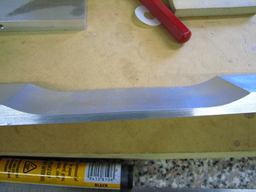
IMG_2135.JPG (48.83 KiB) Viewed 15660 times
I was quite surprised but the arch changes quite dramatically depending on the bar's width (the narrower bars get quite thick through the middle compared to this lower register one) and length, my upper register bars will essentially be just a radius, very little flat/straight area in the centre.
As I say, I'll check these & tweak them once they've come back from anodizing, hopefully they won't alter radically or I may find I have to use my bar measurements sooner than I thought!
I'm still doing the last few naturals & will do the sharps in the next few days then they can go for anodizing.
So while that's going on I'll go back to fix up an old problem I'm still not entirely happy with.......fan timing! The two main drive pulleys are timed perfectly now but the O ring drive up to the respective fan shafts are still varying (O ring is either slipping or stretching & compressing) so I've sourced some posi-drive belt & pulleys which will not allow the shafts to get out of sync with each other! I'll go over this bit in a future post when I've worked out the mechanics of it (smallest posi-drive belt available is longer than my shaft/pulley spacing so I have to work in some sort of easily adjustable tension/slop remover without introducing extra drag).
"Jesus Loves You."
Nice to hear in church but not in a Mexican prison.

User avatar
Kim
Admin
Posts: 4376
Joined: Wed Sep 26, 2007 8:32 pm
Location: South of Perth WA

Re: And now for something completely different

Post by Kim » Sat Nov 26, 2011 10:59 am

Nick wrote: So while that's going on I'll go back to fix up an old problem I'm still not entirely happy with.......fan timing! The two main drive pulleys are timed perfectly now but the O ring drive up to the respective fan shafts are still varying (O ring is either slipping or stretching & compressing) so I've sourced some posi-drive belt & pulleys which will not allow the shafts to get out of sync with each other! I'll go over this bit in a future post when I've worked out the mechanics of it (smallest posi-drive belt available is longer than my shaft/pulley spacing so I have to work in some sort of easily adjustable tension/slop remover without introducing extra drag).
Hey Nick,

How about round urethane belting? You can get it from 2mm to 18mm and in standard "O" ring sizes. I have used 6mm material as the drive belt on a 3 wheel bandsaw and it worked out really well. To join the material you simply heat the ends until they melt a bit, bring them together and hold in place (preferably jigged to ensure good alignment) until they cool, and then trim off the excess at the weld to bring it back in to round...strong as. If concerned about joint strength the material is tubular, (all be it a very small ID) so it will accept a jointing barb pushed up the centre to secure the joint, but I did not bother on the bandsaw (3 speed so it pushes along when stretched onto the large drive pulley) and it has held up just fine for a few years now. The urethane material does flex but not anything like rubber, and to reduce flex and eliminate slippage you simply reduce the size of the belt so it is 'stretched' over the pulleys to remain in tension.

Image

http://www.durabelt.com/roundoringinfo.php

http://www.directindustry.com/prod/dura ... 26276.html

The links and image are just first of the googlator, I do not endorse that particular product or those vendors as I have not dealt with them. Truth is you should be able to get this stuff from most any bearing outlet or from RS Components. The material comes in various hardnesses which are expressed as a "durometer" rating. This also gives and idea of how much stretch the material will have..more stretch = less slip = less resistance to heat..i.e. a belt with a durometer rating of 90A would be considered 'hard' and stretch app 8%. Material rated 83A will be softer and stretch 12%...I am sure you get the idea or have already considered and rejected the idea for some reason but I though I would mention it just in case it could work for you.

Cheers

Kim

User avatar
Nick
Blackwood
Posts: 3642
Joined: Thu Feb 26, 2009 11:20 am
Location: Christchurch, New Zealand
Contact:

Re: And now for something completely different

Post by Nick » Sat Nov 26, 2011 11:42 am

Thanks for that Kim, I did initially think about the Urethane O ring type belts and may still use them (I can at least order a couple and have them handy if the posi drive system proves to be a problem child or I may just try them first & stick with them if they work!). The thing I do like about the Posi drive system however, is that it is essentially another type of timing belt with positive engagement between pulley & belt.
Image
The pulleys have notches which engage in the 'ears' on the polyurethane belt (this crowd supply them in Oz http://www.minibearings.com.au/store/it ... inglecore/) so once engaged the positioning should never change. I've received the belts & pulleys & I ordered the smallest belt size they sold and it doesn't have that much stretch but is just the right size to slip onto the lower pulley when the resonators are on. I just need to take up some of the 'extra' once the belts been put on in the right position. I don't want to overcomplicate the design (I could make it highly technical :roll: ) & I don't want to have it adjust too tight as this will load up the motor, although the motor has a fair amount of torque, probably more than the function it carries out needs but, as Tim Taylor would say.... you can never have too much grunt! Jim also mentioned in his email, the fact that the player sometimes likes to spin the fans up by hand so I need to factor in this as well.
But once I've got the bars tuned & away getting prettied up at the Anodizers I'll sit down and remove the last bits of remaining hair from the top of my head & sort something out.
"Jesus Loves You."
Nice to hear in church but not in a Mexican prison.

ckngumbo
Blackwood
Posts: 102
Joined: Mon Oct 26, 2009 11:41 am
Location: Florida US

Re: And now for something completely different

Post by ckngumbo » Sat Nov 26, 2011 12:39 pm

Geeze I just hope to build something that stays in tune and you're making tuning bars sound easy!
This is a brilliant thread! :cl

User avatar
DarwinStrings
Blackwood
Posts: 1877
Joined: Thu Nov 13, 2008 10:27 pm
Location: Darwin

Re: And now for something completely different

Post by DarwinStrings » Sat Nov 26, 2011 7:40 pm

I guess I shouldn't be surprised that to tune these bars you use the same method that I have used to tune marimba bars but I was.

I hadn't heard of a vibraphone till this thread and then the other day my 14 yo comes home with a recording he had done at school on which he played the vibraphone......more surprises as he is learning guitar at school.

Jim
Life is good when you are amongst the wood.
Jim Schofield

simso
Blackwood
Posts: 1768
Joined: Mon Apr 25, 2011 10:36 pm
Location: Perth WA

Re: And now for something completely different

Post by simso » Sat Nov 26, 2011 8:27 pm

Nick wrote: Hope you guys are still finding some interest in this thread! :D
Most definetly, have watched the progress here from the start with a very keen interest
Steve
Master of nothing,

Do your own repairs - http://www.mirwa.com.au/How_to_Series.html

User avatar
charangohabsburg
Blackwood
Posts: 1818
Joined: Sat Oct 16, 2010 1:25 am
Location: Switzerland

Re: And now for something completely different

Post by charangohabsburg » Sun Nov 27, 2011 1:15 am

Nick wrote:There's a really good paper written on the subject by a guy called Jeff La Favre here.
Wow! Thanks for this one Nick! It will keep me occupied a couple of hours, for now I just browsed through and I already discovered some interesting details, such as those non-perpendicular node lines which you would not discover in your metal bars. I guess you tuned the bars up to the third overtone, right? :lol:
Markus

To be stupid is like to be dead. Oneself will not be aware of it.
It's only the others who suffer.

User avatar
Nick
Blackwood
Posts: 3642
Joined: Thu Feb 26, 2009 11:20 am
Location: Christchurch, New Zealand
Contact:

Re: And now for something completely different

Post by Nick » Thu Jan 12, 2012 12:09 pm

Well the journey is almost completed! Frame has been powdercoated 'Electro' anodised aluminium colour & the bars are Anodised. The bars came back a little darker than I expected but the powdercoating is almost an exact match so with the few 'black' accents on the thing, it's all looking rather sharp I must say (not a comment on my own workmanship...just a comment on the colour scheme)!
I'm just waiting on some vinyl cuts of my guitar logo (scaled up to fit) & a label from the signwriters & this puppy is finished & will be delivered to the customer on Saturday. He's been in & we fine tuned things to fit him & he also hit a few bars which produced a slight buzz as the bars 'bounced' on the damper bar padding during the note's decay phase. I was using softer mallets when making the vibes so it hadn't shown up this problem before & also the customer hits the bars alot harder than I do & also uses really hard mallets but it should only take a couple of hours of playing around tonight to cure this problem.It is only a few bars on the # frame so may just be a case of localised 'extra' padding(meaning less than a millimeters worth).

I managed to get the fans working in Unison so here's a few pics of the tensioner mechanism I was working on when I last posted.
Here's a pic of the pieces that go into each tensioner
IMG_2140.JPG
IMG_2140.JPG (48.9 KiB) Viewed 15512 times
The springs I had to make as there were no commercially made ones suitable (either not enough tension or too much!). Here's a 'before & after' shot, the spring steel wire we have here in our workshop in several different diameters then we just wind the spring to suit in a standard lathe but just turn the chuck by hand.
IMG_2136.JPG
IMG_2136.JPG (49.06 KiB) Viewed 15512 times
And fitted to the tensioner arm
IMG_2138.JPG
IMG_2138.JPG (56.16 KiB) Viewed 15512 times
I purchased some stepped bearings, again from VXB, to carry the tensioner 'wheel'
IMG_2141.JPG
IMG_2141.JPG (37.64 KiB) Viewed 15512 times
The whole assembly was screwed to the side rail of each resonator rack
IMG_2144.JPG
IMG_2144.JPG (60.36 KiB) Viewed 15512 times
When fitting the resonators to the frame and subsequently the belt to the pulleys, give the top of the lever a bit of thumb which moves it out of the way & lets you fit the belt to both pulleys, you just let go of the lever and it swings in and tensions the belt.
IMG_2147.JPG
IMG_2147.JPG (40.8 KiB) Viewed 15512 times
I haven't got a shot of it fully completed just yet (will take a few with the 'stickers' on it once I have them) but here's a few of it almost complete.
Speed control/motor drive unit (the rectanglular plate to the left is yet to have a label fixed in the recess)
IMG_2150.JPG
IMG_2150.JPG (35.9 KiB) Viewed 15512 times
Secondary Drive belt to the fans
IMG_2151.JPG
IMG_2151.JPG (42.88 KiB) Viewed 15512 times
And just a few shots of nothing in particular :oops:
IMG_2153.JPG
IMG_2153.JPG (61.27 KiB) Viewed 15512 times
IMG_2155.JPG
IMG_2155.JPG (56.3 KiB) Viewed 15512 times
Looking up from underneath the bars (the little row of holes in the beam are screw access to remove the hooks), you can also see some 'shiny' areas on a few of the bars, these are where I fine tuned the first harmonic after the anodising, I was pleasantly surprised to see that the Anodising had no effect on the tuning so if I make any more I know I only need to leave the bars a couple of cents sharp if at all!
IMG_2159.JPG
IMG_2159.JPG (52.64 KiB) Viewed 15512 times
IMG_2161.JPG
IMG_2161.JPG (98.97 KiB) Viewed 15512 times
And finally just a quick shot of the vibes in their unadorned state.
IMG_2152.JPG
IMG_2152.JPG (76.14 KiB) Viewed 15512 times
I'll take a few shots before it goes out the door & I'll try to get the customer to agree to have a brief vid taken of him playing it so that you guys can hear it all in action.
"Jesus Loves You."
Nice to hear in church but not in a Mexican prison.

Kamusur
Blackwood
Posts: 754
Joined: Thu Dec 30, 2010 10:08 pm

Re: And now for something completely different

Post by Kamusur » Thu Jan 12, 2012 5:09 pm

This is the bomb Nick no doubt about it.

Steve

Post Reply

Who is online

Users browsing this forum: No registered users and 309 guests