DIY Sig Gen/Amp unit for Chladni patterns

You can ask questions here about Trevor and Gerard's exciting new book on Luthiery.

Moderators: kiwigeo, Jeremy D

User avatar
Trevor Gore
Blackwood
Posts: 1605
Joined: Mon Jun 20, 2011 8:11 pm

DIY Sig Gen/Amp unit for Chladni patterns

Post by Trevor Gore » Thu Jun 29, 2017 12:42 am

Those who have experienced the 3 day modal tuning course may remember my 1970's era 12kg power supply/sig gen/amp unit, which works sort of fine, but weighs a ton, so is not the best to fly with when I do overseas courses. One of the problems with this old unit (apart from the fact that it could cark it at any time) is that it needs a separate device to measure frequency.

The problem with commercial signal generators is that a separate amp is required to power the loud speaker, and the frequency control is often via digital buttons rather than the analogue knobs which I prefer. With the Bradley sig gen unit no longer available since Don's untimely passing, I thought I'd see if I could put together a unit from kit parts.

I wanted an analogue sig gen (which only actually means sine waves, for Chladni purposes) so I could adjust it with knobs, I wanted a digital readout, so that meant a counter unit and I needed a power amp to drive the Chladni speaker. I also wanted it to work on both 110v and 240v without having to switch voltages manually.

This is what I came up with and it does everything I wanted whilst weighing less than 1 kg but puts out a real 30w RMS:
DSCF0040s.jpg
DSCF0040s.jpg (96.43 KiB) Viewed 115433 times
DSCF0042s.jpg
DSCF0042s.jpg (123.28 KiB) Viewed 115433 times
If anyone is interested in the design/build details, post to say so and I'll fill in the details. Whilst you don't need to be an electronics wizz to build this, you do need to know what you're doing. I'd say it's also very difficult to pull this off without a fair amount of gear, including access to a solder station (of course), a bi-polar bench power supply, a multimeter and an oscilloscope.

williamp
Gidgee
Posts: 6
Joined: Mon Jan 06, 2014 4:44 pm

Re: DIY Sig Gen/Amp unit for Chladni patterns

Post by williamp » Thu Jun 29, 2017 8:31 am

Hi Trevor,

I would like to know more about the sig/gen.

William

legin

Re: DIY Sig Gen/Amp unit for Chladni patterns

Post by legin » Thu Jun 29, 2017 8:39 am

Hi Trever

Im very keen to learn more about this too.
I have built a few guitar amps in the past so I have a bit of gear.
I don't have a scope (I have always wanted one) but I may have an excuse to buy one now.

User avatar
kiwigeo
Admin
Posts: 10580
Joined: Sat Sep 29, 2007 5:57 pm
Location: Adelaide, Sth Australia

Re: DIY Sig Gen/Amp unit for Chladni patterns

Post by kiwigeo » Thu Jun 29, 2017 11:13 am

I wasn't aware that Bradley had passed away. A nice bloke....I bought one of his units and had some very useful conversations with him about it's use.
Martin

User avatar
Trevor Gore
Blackwood
Posts: 1605
Joined: Mon Jun 20, 2011 8:11 pm

Re: DIY Sig Gen/Amp unit for Chladni patterns

Post by Trevor Gore » Thu Jun 29, 2017 10:04 pm

kiwigeo wrote:
Thu Jun 29, 2017 11:13 am
I wasn't aware that Bradley had passed away. A nice bloke....I bought one of his units and had some very useful conversations with him about it's use.
Don was a really nice bloke. He attended the first modal tuning course in Fort Bragg, CA - one of the two I did with Brian Burns. Don lived not far away and we spent an afternoon at his place - along with his pet lamas and vintage cars! A real gentleman, sadly missed.

User avatar
Trevor Gore
Blackwood
Posts: 1605
Joined: Mon Jun 20, 2011 8:11 pm

Re: DIY Sig Gen/Amp unit for Chladni patterns

Post by Trevor Gore » Thu Jun 29, 2017 11:00 pm

OK, for those who want to know more, this is where I started. This "tutorial" is going to be in bits as I get to writing it.

A couple of key issues:
1) Ultimately, you need to driver the speaker (4" diameter) with a signal that has no DC offset. Over the years, I've heard of a lot of people blowing speakers with relatively little apparent power (and associated volume) and it occurred to me why this was happening - the output from whatever they were using as an amp was operating between 0 and + (say) 12v, so the DC offset was killing the speaker. So the power amp (at least) needs a dual power supply. If you want the full 30 watts (you don't need it) you will need a +15v and - 15v dual power supply driving a 4 ohm speaker. Ultimately, I ended up finding that a +12v and - 12v dual power supply (trimmed up to a slightly higher voltage for reasons I will get to later) driving a 8 ohm speaker was more than adequate, so that is what I used. I got the switch mode power supplies (SMPS's) from here. For the dual supply, two of these units are required.
2) It helps to keep things simple if everything else can run off the +/- 12v power supply, so I tried to do this and failed. In particular, I couldn't get the dual supply XR2206 circuit linked to above to work. I could get square waves, but not sine waves. So I moved to another solution. However, first thing is to read the stuff in the link above and download the two data sheets linked (TAN 005 and XR 2206) which detail both dual and single power supply circuits for the XR 2206. There are a number of XR 2206 kits available this being a cheap one (worth it for just the components), but this was the one I used. It seems it is currently out of stock, but a search will likely turn up others. The reason for using the RHelectronics kit was that the pcb allowed for the trim pots to shape the sine waves, which is important.

Enough for this evening. I'll go through the other components and issues in a following post.

Dave M
Blackwood
Posts: 594
Joined: Tue Jul 15, 2014 6:44 am
Location: Somerset UK

Re: DIY Sig Gen/Amp unit for Chladni patterns

Post by Dave M » Fri Jun 30, 2017 9:10 am

Man I really think I will stay with VA put through an old domestic amplifier!
------------------
Dave

User avatar
kiwigeo
Admin
Posts: 10580
Joined: Sat Sep 29, 2007 5:57 pm
Location: Adelaide, Sth Australia

Re: DIY Sig Gen/Amp unit for Chladni patterns

Post by kiwigeo » Fri Jun 30, 2017 9:25 am

Trevor has missed out one important item on the component list: https://www.ebay.com/p/Propeller-Nerd-H ... 2003494224
Martin

User avatar
Trevor Gore
Blackwood
Posts: 1605
Joined: Mon Jun 20, 2011 8:11 pm

Re: DIY Sig Gen/Amp unit for Chladni patterns

Post by Trevor Gore » Fri Jun 30, 2017 9:33 am

Dave M wrote:
Fri Jun 30, 2017 9:10 am
Man I really think I will stay with VA put through an old domestic amplifier!
Nothing wrong with that for a home unit!

User avatar
Trevor Gore
Blackwood
Posts: 1605
Joined: Mon Jun 20, 2011 8:11 pm

Re: DIY Sig Gen/Amp unit for Chladni patterns

Post by Trevor Gore » Wed Jul 05, 2017 5:37 pm

I've written, so far, about the power supplies and the sig gen module.

The total unit comprises 5 electrical modules: the twin power supplies, the sig gen module, a counter module, a pre-amp module, and a power amp module.

Here are the details on the counter module I used. The counter module is this one. It is a pretty easy-to-put-together kit and basically just needs assembly. Here's a link to the site of the guy who designed it and there is some more info there (not that you really need it). The instructions talk about setting a test point voltage to 2.5v, which is done by changing resistor R 13, which I had to do. Increase the resistance value to increase the TP voltage. The input signal to the counter needs to be lower in voltage than the counter module's supply voltage, and always positive. I used the square wave output direct from the sig gen module to drive the counter and it satisfies the above requirements without any more signal conditioning. The counter modules needs between 7 and 9v supply. I used 9v, which I also used to supply the sig gen module. I had initially intended to use 12v for the sig gen, but it "hunted" i.e was unstable at in the low frequency range that we typically use. I don't know the details of why that happened, but reducing the supply voltage to 9 v fixed it. (The sig gen is capable of running at supply voltages up to 26v, according to its specs). The 9v supply was obtained by dropping from the power supply delivery voltage using a series of diodes mounted on the pre-amp board, which I will explain more when I get to that bit. There is a trim capacitor on the counter board. Adjusting it didn't seem to affect the module's operation. The PIC micro-controller comes per-programmed in this kit, so no need to worry about that.

User avatar
Trevor Gore
Blackwood
Posts: 1605
Joined: Mon Jun 20, 2011 8:11 pm

Re: DIY Sig Gen/Amp unit for Chladni patterns

Post by Trevor Gore » Thu Jul 06, 2017 10:13 pm

Having covered the power supplies, the sig gen module, and the counter module, the next one I'll go over is the power amp module. I used a mono, 30watt RMS, D class power amp which is absolutely tiny (about a third the size of a credit card) yet it seems to deliver the goods. The unit I used was this one. It comes with essentially nothing by way of information and I assumed it was supplying just current gain. I was wrong! Eventually I managed to find the main chip datasheet, which you can download from here. The voltage gain in mono configuration (BTL) is 36dB. So that is a voltage amplitude gain of ~60 and a power gain of ~4000. The pre-amp module is zero voltage gain (I'll get to the design of that shortly), so you need approximate 0.5v peak to peak from the sig gen unit (which it will easily deliver) to be able to saturate the power amp.

In the next post I'll go over the design of the pre-amp and the other bits and pieces that need to go on the pre-amp board.

I hope some of you are still following this...

User avatar
lamanoditrento
Blackwood
Posts: 588
Joined: Thu May 05, 2016 9:50 am

Re: DIY Sig Gen/Amp unit for Chladni patterns

Post by lamanoditrento » Fri Jul 07, 2017 7:56 am

Trevor Gore wrote:
Thu Jul 06, 2017 10:13 pm
I hope some of you are still following this...
Not really, but I read it all the same with vague thoughts of 'someday'
Trent

williamp
Gidgee
Posts: 6
Joined: Mon Jan 06, 2014 4:44 pm

Re: DIY Sig Gen/Amp unit for Chladni patterns

Post by williamp » Fri Jul 07, 2017 11:35 am

Hi Trevor,

Still following with interest. Thanks for taking the time to write it up.

William

User avatar
kiwigeo
Admin
Posts: 10580
Joined: Sat Sep 29, 2007 5:57 pm
Location: Adelaide, Sth Australia

Re: DIY Sig Gen/Amp unit for Chladni patterns

Post by kiwigeo » Fri Jul 07, 2017 2:22 pm

Definitely still with this.....spent most of my youth building effects boxes and other devices that generally drove my parents crazy.

IMHO there's a definite market for this instrument now that Don Bradley has gone.
Martin

User avatar
Trevor Gore
Blackwood
Posts: 1605
Joined: Mon Jun 20, 2011 8:11 pm

Re: DIY Sig Gen/Amp unit for Chladni patterns

Post by Trevor Gore » Sat Jul 08, 2017 12:00 am

OK. On to the next stage.

We've covered the power supplies, the sig gen module, the counter module and the power amp module. Next is the pre-amp module.

The pre-amp module has three major tasks: it allows the coupling of the sig gen module to the power amp, it provides for a volume control for the power amp and it supplies the 9 volt supply for the sig gen and counter. Here's the circuit design:
Visio-Preamp drawing.jpg
Visio-Preamp drawing.jpg (53.3 KiB) Viewed 115207 times
Initially, I thought it would be pretty easy to connect the sig gen to the power amp, but a direct (DC) connection just would not work. I couldn't figure a good explanation why. A bit of googling sorted of hinted that running two modules off different parts of twin, linked SMPS's doesn't work, but gave no explanation why. It seems that this digital circuitry (the SMPS's and the D class amp) like to "float", so if you tie some part of the circuit to ground somewhere you have a problem; but I needed a ground for the analogue circuitry. I tried decoupling with various configurations of capacitors, but couldn't get that to work either, so eventually decoupled using the 220uF decoupling capacitor on the input to get rid of the DC offset out of the sig gen, then coupled to the power amp using a mini coupling transformer. The FET op amps are effectively infinite input impedance, so the 47k resistor is there so that the non-inverting input doesn't just integrate up to the rail voltage. The 10k pot is the main volume control instead of using the volume control on the sig gen itself (which is set to a fixed level). The output from the second op amp (both op amps are on the same DIL 8 pin chip) drives the primary of the coupling transformer, with the secondary being ultimately connected to the input of the power amp. The centre tap isn't used.

The string of diodes (I bought a pack of 100 many years ago for some project I can't remember and have heaps left) drop 0.6v per diode regardless of current draw. Wanting exactly 9v for the sig gen and counter modules and max volts on the power amp, I set the trimmers on the SMPS units to give me 13.2 volts and then used seven diodes to drop this back to the 9 volts I wanted.

So all-in-all, this module is far from an elegant piece of circuitry, but it does the job. I built it on a bit of Vero board.

If anyone else builds this, with more electronics experience than me (wouldn't be hard!), let us know what the root cause of the coupling problems are and please suggest a neater circuit if you can.

The components all came from Jaycar. The diodes are Cat # ZR1005, the op amp is Cat # ZL3072, the coupling transformer is Cat # MM2534. The other parts are just standard circuit components either from Jaycar or my box of electrical bits and should be easy to source.

The next piece will be on the set-up of the various modules and unit testing.

User avatar
Trevor Gore
Blackwood
Posts: 1605
Joined: Mon Jun 20, 2011 8:11 pm

Re: DIY Sig Gen/Amp unit for Chladni patterns

Post by Trevor Gore » Mon Jul 10, 2017 12:49 am

For the unit set-up and testing you'll need an adjustable bench power supply, a multimeter and an oscilloscope.

We'll start with the sig gen module.

The XR 2206 chip produces square waves, sine waves and triangular waves and, if you want, you can configure a box with a heap of switches which will get you all of these waveforms and (with another selector switch) a very wide range of frequencies. I thought about doing this, then thought that for Chladni patterns I only need a narrow frequency range and only sine waves. So, keeping it simple, I decided to dispense with a lot of the complexity that a huge amount of versatility requires. The sig gen modules I linked to above can be configured, by switching between components, for a wide rage of frequencies. Wanting only a narrow range, I only populated the circuit board positions for the components I needed.

Deep in the specs of the XR2206 is a formula giving the frequency output for a combination of resistors and capacitors. I wanted a range that went from ~40Hz to ~2kHz without having to switch components. The formula is F=1/(RC). Obviously, as R increases, F decreases, which poses a minor problem. For a fairly linear response to turning a knob on a potentiometer, you need a log (A type) potentiometer. That in itself is no problem as log pots are easy to source. But if you want the knob to turn clockwise as you increase the frequency, you need a reverse taper (C type) log pot, which are like hen's teeth. However, left handed guitarists use left hand pots on things like left handed Strats, so the music trade is not a bad place to go looking for them, but they really only come in two values 250k and 500k (to suit Strats and Les Pauls). I sourced a 250k pot from here. What I really wanted was one of these, but they won't ship to Aus.

So to get the frequency range I wanted, I used a set resistor (R5 on the RHelectronics circuit) of 4.7k, a coarse frequency adjust using a C250k pot (rev. log) and a fine frequency adjust using a B10k pot (linear- which can be used "left hand" just by reversing the wiring) all in combination with a 100nF capacitor. Using the F=1/(R*C) formula, this gives a nominal minimum frequency of 37.7Hz (1/(100n * (10k+250k+4.7k)) and a nominal max frequency of 2127Hz (1/(100n * 4.7k)). The two pots are mounted on the box with trailing wires to their nominal circuit board positions.

The gain pot on the sig gen board is redundant because the gain control is via the preamp. To save room in the box I used, I substituted a 4.7k preset in the gain pot position, so I could still do a bit of tweaking to set the max amplitude.

The rest of the set-up is as per the instructions with the sig gen kit. Set the voltage on the bench power supply and feed the sig gen with +9v/0v. As mentioned previously, I had intended to use 12v, but the circuit was unstable at low frequencies and moving down to 9v fixed that. Check the sine wave output on your scope and adjust the two trim pots to fine tune the shape of the sine wave. Set the gain preset to give around 0.5v peak-to-peak on the sine wave output. Check the square wave output, which should switch at something a little inside the rail voltage. Without adding more circuitry, the amplitude is not adjustable, but it is fine as it is for feeding directly to the counter module.

That pretty much completes the component selection, set-up and unit testing of the sig gen.

User avatar
Trevor Gore
Blackwood
Posts: 1605
Joined: Mon Jun 20, 2011 8:11 pm

Re: DIY Sig Gen/Amp unit for Chladni patterns

Post by Trevor Gore » Mon Jul 10, 2017 9:06 pm

And so to the next installment...

Next up is the counter module. This is pretty straight forward to set up. Set the bench supply to deliver +9v/0 and power up the module. It has an on/off switch, which, once you have the unit working, should be left on. Inject a waveform into the input (must always be positive voltage and less than the supply voltage and check that it counts. I tried various waveforms from my antique sig gen unit and it seemed to count them all accurately. Check that the test point voltage is very close to 2.5v, and if not change the value of R13 until it is close (within ~0.1v). Raising the resistor value raises the voltage.

Connect the square wave output from the sig gen module and ensure that the two modules will work together. Check with the scope that you are getting the right frequency count. Any randomness in the frequency count seems to be due to noise on the input (the square wave). This was apparent to me when I was trying to run the sig gen off a 12v supply and some "pulsing" was going on which screwed up the count.

Disconnect the sig gen and counter modules from the bench power supply and reset the supply voltage to +13.2 volts and -13.2 volts. Connect the pre-amp module to the power supply and inject a waveform into the input. You should have a very similar peak to peak voltage on the output (across the secondary of the coupling transformer), but there should be no DC offset. Connect a resistor between the end of the diode string and ground (a 1k ohm value is as good as any) and measure the voltage across the resistor. You should be seeing very close to 9v. Adjust the power supply voltage until you have 9.0v and measure the actual voltage on the power supply terminals. Make a note of this, as this is the voltage you will need to trim the SMPS's to.

You can now string test the sig gen, counter and pre-amp modules. Connect the sig gen and counter to the 9v supply off the pre-amp board, connect the the square wave output from the sig gen to the counter module and connect the sine wave output from the sig gen to the pre-amp input. Check that you have the the same frequency of sine wave on the output of the pre-amp as you have on the output of the sig gen and that the counter is reading this correctly. Check that you can vary the amplitude of the output from the pre-amp between 0 and ~0.5v peak-to-peak using the pre-amp's level control pot.

Once you have all that running smoothly, you can connect up the power amp, but before you do, it's good to have a load for the power amp to drive. So the next post will be a short diversion into building the speaker unit.

User avatar
Trevor Gore
Blackwood
Posts: 1605
Joined: Mon Jun 20, 2011 8:11 pm

Re: DIY Sig Gen/Amp unit for Chladni patterns

Post by Trevor Gore » Tue Jul 11, 2017 11:29 pm

This evening's installment covers the building of the speaker unit. I think it is the part of the system that seems to get the least attention and is likely the root cause of a lot of issues when trying to produce Chladni patterns. So, a few "rules of thumb"to start with...

First, the speaker needs to be quite small. The reason for this is that to excite some of the higher frequency modes, you need to excite over an antinode. Because at higher frequencies the soundboard has divided up into quite small vibrating segments, each adjacent one in anti-phase to the next, you need quite a small speaker to be able to excite over a single anti-node region. A larger speaker will sit over adjacent anti-node regions of opposite phase to each other, with only one being in phase with the drive, whilst the other is out of phase with the drive. The net result is that not a lot happens.

Second, you need a speaker that will produce low frequencies well. In general, small speakers don't work well at low frequency, or are very inefficient. But small speakers generally won't take huge amounts of power, either.

Third, you need to enclose the speaker. They get much louder in front if you can cut out the sound from the back of the speaker which is out of phase and radiating straight at you.

So we end up looking for a smallish speaker that is efficient at low frequencies and that will handle a fair amount of power.

The answer is a four inch (100mm) speaker. Smaller ones don't produce the low frequencies we need. My original unit, which works really well, used a 4", 8 ohm driver from a stereo pair of full range car speakers bought years ago from Jaycar. They don't currently seem to stock the identical driver, but they have similar units in their catalog. I mounted it in an enclosure made from a piece of 140mm outside diameter electrical conduit (probably nominal 5" (125mm) conduit), mounting the speaker at one end on a MDF baffle and closing the other end with an MDF disc.

For the new Chladni box of tricks, I thought I'd build a smaller speaker unit, making it from a piece of 100mm (nominal) uPVC low pressure pipe using a closing cap as a baffle and another cap on the other end. Old unit on the left, new unit on the right:
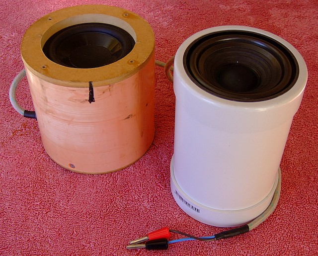
DSCF0060s.jpg
DSCF0060s.jpg (125.82 KiB) Viewed 115066 times
The new unit uses a 4" Monacor driver with an efficiency of 91dB, 1W/1m, which is about as good as it gets. The frequency response is 70Hz to 7kHz.
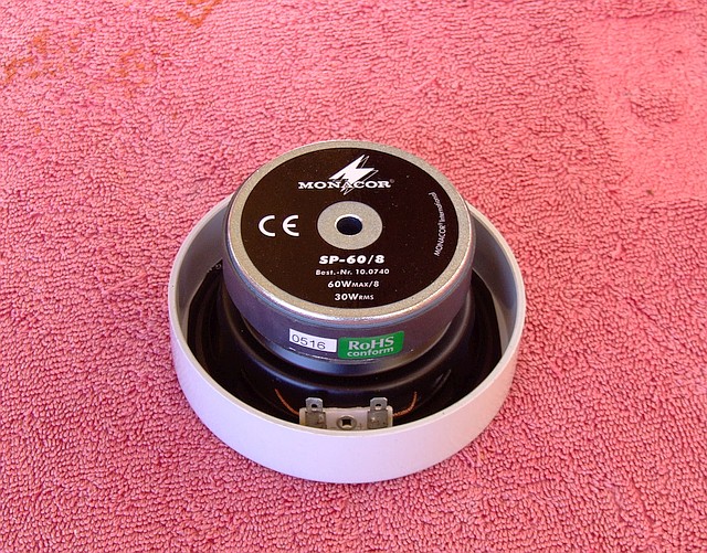
DSCF0057s.jpg
DSCF0057s.jpg (157.59 KiB) Viewed 115066 times
The assembly is pretty self explanatory. I needed to trim away a bit of the speaker top flange so it would fit in the pipe cap. I cut the hole out roughly with a jig saw and then found a bearing from my binding cutter kit which fit on a half inch pattern follower bit and ran the bearing around the cap flange to produce a cutout of exactly the right size. (Sometimes you get lucky...) The speaker is held in position by being trapped between the pipe end and the well rammed on cap.
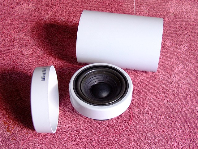
DSCF0059s.jpg
DSCF0059s.jpg (136.71 KiB) Viewed 115066 times
According to the power amp data sheet, (Fig 9), either a 4 ohm or 8 ohm speaker with a 26v supply voltage (what we have) will deliver close to 30 watts. I might experiment with a bit of wadding in the pipe to see if it makes much difference. Otherwise, wire it up and it's good to go.

User avatar
Trevor Gore
Blackwood
Posts: 1605
Joined: Mon Jun 20, 2011 8:11 pm

Re: DIY Sig Gen/Amp unit for Chladni patterns

Post by Trevor Gore » Thu Jul 13, 2017 10:49 pm

And on to the power amp.

There's really not much to say. It's a tiny (physically) class D amp, that pushes out 30W RMS. It can be powered with a wide voltage range, but I wired it across the twin supply so the positive supply was +13.2v and the negative was -13.2v (so 26.4v, cf a max rating of 36v and a min of 10v). Then there's just the input and the output. The input seems to like to "float" relative to the power supply and the output can be taken straight to the load, i.e. the speaker unit. I tested it using the bench power supply set for + and - 13.2v and it worked fine. There is nothing to trim or adjust. Remember that this thing has a gain of 36dB, (voltage gain of ~60) so it doesn't need a whole lot to saturate it. Set the max level on the sig gen (~ 0.5v peak to peak) using the pre-set and use the 10k ohm pot in the pre-amp circuit as the volume adjust. I wired the output to black and red 4mm banana sockets.

Moving right along to the SMPS's themselves, I've left these until last so you aren't tempted to use them prior when setting up the other modules. These things "do what it says on the can", but can be a bit idiosyncratic. Also, the mains input terminals are pretty close to the low voltage output terminals and you really don't want any mix-ups there. Here's how I wired them:
SMPS Connex.jpg
SMPS Connex.jpg (39.8 KiB) Viewed 115019 times
The voltage trims have quite a wide scope and you can dial up to around 14v on this model. Another thing to note if you substitute a different SMPS is that you may find that the DC negative terminal is also connected to ground, which means that you can't series connect them like I've shown unless you break that connection, because you just get a direct short to ground on the output.

I did not want the power cable permanently connected to my box, so I used an IEC type connector and plugged into the box via this switch/fuse (1A quick blow)/socket arrangement from Jaycar.

A final thing to note is that as wired, these supplies don't always switch on properly, with one or other of them failing to "fire". When all is connected up, this results in interference type noise from the speaker. I have no idea why this is. If I power down, wait about 2 secs and power up again, they invariably behave. Someone with experience in this area might let us know why and what the fix is. Possibly a requirement for some sort of suppressor across the mains input; IDK.

You now have a chance to string test all the modules. The power amp is connected across the +13.3v and -13.2v from the SMPS; the pre-amp takes +13.2v, 0v, -13.2v from the SMPS; the sig gen and counter take +9v and 0v off the pre-amp board. From the sig gen, the sine + and - connect to the pre-amp input; the square wave + and - connect to the counter module; the pre-amp output from the coupling transformer connects to the power amp input; the power amp output connects to the speaker. Check all your interconnections before you power it up.

The final piece (I think!) will be how it all fits in the box.

Dave M
Blackwood
Posts: 594
Joined: Tue Jul 15, 2014 6:44 am
Location: Somerset UK

Re: DIY Sig Gen/Amp unit for Chladni patterns

Post by Dave M » Fri Jul 14, 2017 7:34 am

If I may add something about the speaker enclosure... I boxed in a car speaker - they seem to be a useful source of 4 inch speakers - then found that the box was a bit awkward to hold. And you really don't want to drop the little darling on a guitar so added handles.

I intended to support it with a bungee cord but never quite got around to it, but this would also help prevent mishaps!

Cheers Dave
Attachments
speaker 1 small.jpg
------------------
Dave

User avatar
Trevor Gore
Blackwood
Posts: 1605
Joined: Mon Jun 20, 2011 8:11 pm

Re: DIY Sig Gen/Amp unit for Chladni patterns

Post by Trevor Gore » Sun Jul 16, 2017 10:42 pm

Dave M wrote:
Fri Jul 14, 2017 7:34 am
And you really don't want to drop the little darling on a guitar so added handles.
Yep, the magnet in a decent driver weighs quite a bit. Certainly not to be dropped. The 4" uPVC is easy to hold by the end caps. I don't glue the caps on mine, but have them fixed with small screws through the flanges. If anyone makes ones of these, either glue them or screw them before you hold the unit over someone else's guitar!

User avatar
Trevor Gore
Blackwood
Posts: 1605
Joined: Mon Jun 20, 2011 8:11 pm

Re: DIY Sig Gen/Amp unit for Chladni patterns

Post by Trevor Gore » Sun Jul 16, 2017 11:42 pm

And finally, fitting it all in the box.

The box I used, from the ubiquitous Jaycar, was this one, an ABS enclosure sized at 171 x 121 x 80mm, and it's a pretty tight fit as you can see:
DSCF0042s.jpg
DSCF0042s.jpg (123.28 KiB) Viewed 114930 times
I wanted mine to stand on its end, because it will be most often used when I'm teaching. The display is visible to an audience and I have easy access to the knobs on the top. You may prefer to have the knobs just below the display on the top of the box when it is sat flat, and I think there would be room for them there with the rest of the internals laid out the same way.

Going around the modules anticlockwise from the bottom left, first there is the IEC mains socket, which has an integral switch and fuse holder. I think I had to clip one of its terminals to give a little more clearance on the first of the pair of SMPS's mounted low to get the weight low for stability. Then there are the two 4mm banana sockets for the speaker output and immediately above, mounted to the side of the box on the white spacer posts, is the tiny 30W RMS class D power amp. Above the power amp, mounted off the base (back) of the box is the sig gen unit. The two blue things immediately below the centre pot are the sine wave shaping pre-sets, and on the lower edge of the board, below the blue pre-sets, is the level setting pre-set for the sig gen board. The three pots on the top side, right to left, are fine frequency adjust, coarse frequency adjust and level adjust. The frequency pots are just wired via trailing leads to where they would normal sit on the pcb. The level adjust is wired to the pre-amp board, which is the piece of Vero board, top left, also mounted off the base (back) of the box. The counter is mounted off the top of the box using appropriately sized spacer pillars to keep the frequency display as close to the viewing window as possible. I used a small piece of smoked perspex over the cutout for the display window.

Since that pic was taken, I've made one more mod to the circuit. I broke into the sine line linking the sig gen sine out to the pre-amp input and wired them to a switched 3.5mm stereo jack socket that I mounted on the side of the box just above the IEC socket. What this does is let me plug my computer (or any other signal/music source) into the box so I can use it as a 30W power amp. The switched socket cuts the signal from the sig gen to the pre-amp when a 3.5mm jack is plugged in. The sig gen still runs, and its frequency is displayed, but the level control now works on the injected signal and the sine wave is by-passed. Whilst not exactly hi-fi, the sound quality through the Monacor driver in its bit of pipe is not half bad. Certainly a truckload better than typical laptop speakers. So that saves me lugging around another piece of kit. Whether anyone else has a sufficient use for such a facility to bother wiring it in, is up to them.

So I think that's it.

Any questions?

User avatar
Trevor Gore
Blackwood
Posts: 1605
Joined: Mon Jun 20, 2011 8:11 pm

Re: DIY Sig Gen/Amp unit for Chladni patterns - update

Post by Trevor Gore » Wed Aug 02, 2017 10:27 pm

In this post, I mentioned that the power supplies don't always switch on properly. They can also be somewhat noisy, in terms of "ripple" getting through to the output of the power amp, which I guess is a function of them being really cheap power supplies intended for powering LED strings. Whilst looking for a different type of power supply for another application, I stumbled across a dual supply, the Mean Well RD-3513, which is really well suited to this application. It seems that the reason I hadn't found it before is that it is rated at +13v and -13v rather than the +/-12v that I had been searching for previously. The spec says it is adjustable over the range +/-11.5v to +/-15.5v, so it covers the range needed for this application perfectly. I sourced one for $22 from Mouser Electronics. Very fortuitously, it also fitted into the enclosure, once the previous SMPS's had been removed. It works really well. No start up issues and a lot quieter than the previous units. Almost no extraneous noise from the power amp getting through to the speaker. I guess you get what you pay for!

So here is the revised power connection diagram...
Visio-SMPS Connex Dual_2.jpg
...and here is how I got it in the box:
DSCF0147cs.jpg
DSCF0147cs.jpg (136.21 KiB) Viewed 114571 times
The Aux. input that I mentioned here (at the bottom of the post) is mounted just above the mains input socket...
DSCF0148s.jpg
DSCF0148s.jpg (96.52 KiB) Viewed 114571 times
...and it all works very nicely.
DSCF0154cs.jpg
DSCF0154cs.jpg (91.78 KiB) Viewed 114571 times

User avatar
kiwigeo
Admin
Posts: 10580
Joined: Sat Sep 29, 2007 5:57 pm
Location: Adelaide, Sth Australia

Re: DIY Sig Gen/Amp unit for Chladni patterns

Post by kiwigeo » Wed Aug 02, 2017 10:57 pm

Thanks for the excellent run down on your Chladni kit Trevor.....
Martin

User avatar
Trevor Gore
Blackwood
Posts: 1605
Joined: Mon Jun 20, 2011 8:11 pm

Re: DIY Sig Gen/Amp unit for Chladni patterns

Post by Trevor Gore » Thu Aug 03, 2017 12:21 pm

kiwigeo wrote:
Wed Aug 02, 2017 10:57 pm
Thanks for the excellent run down on your Chladni kit Trevor.....
No worries, Martin.

Having a proper dual supply means I can probably re-do the pre-amp with a zero offset facility to null out the DC from the sig gen and direct couple it all, losing the coupling capacitor on the input to the pre-amp and the coupling transformer on its output. Would likely still need a coupling capacitor for the aux. input, though.

However, it works fine as it is, so I'll leave it for now.

Post Reply

Who is online

Users browsing this forum: Google and 7 guests